Announcement

Collapse
No announcement yet.

Question on the Iowas 1.5" STS outer belt plate

Collapse
X
 
  • Filter
  • Time
  • Show
Clear All
new posts

  • Question on the Iowas 1.5" STS outer belt plate

    Hello WAFF....its been a while

    I have a QUESTION on the Iowas 1.5" STS outer belt plate...
    someone wrote....
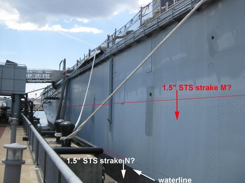
    "strakes M-N at waterline were 1.5" STS to act as torpedo trigger"

    My question is how much of the plate actually extends below the waterline as torpedoes average a +/-10 foot running depth, I would think at least that much, if not more extended below the WL....and at an average STS plate height of about 10 feet....maybe a 20+ foot height (2 strakes M-N) is possible ? (see pic below)

    Anybody know the actual height of 1.5" STS belt ? and could it actually act as torpedo trigger?


  • #2
    test password ...prob

    Comment


    • #3
      Here are link to the Booklet of general plans for the NJ in 1984 fit.
      It should answer your question.


      http://www.hnsa.org/doc/plans/bb62.pdf

      Comment


      • #4
        Originally posted by Gun Grape View Post
        Here are link to the Booklet of general plans for the NJ in 1984 fit.
        It should answer your question.


        http://www.hnsa.org/doc/plans/bb62.pdf
        Well Im a clutz with diagrams but I gather from cross section that "N" is on top and "M" is on bottom, not much of strake N is below waterline ? hmmmm how can it be a torpedo trigger
        does any body know how to scale the drawing to approximate the height of the two strakes

        Comment


        • #5
          Originally posted by petsan View Post
          Well Im a clutz with diagrams but I gather from cross section that "N" is on top and "M" is on bottom, not much of strake N is below waterline ? hmmmm how can it be a torpedo trigger
          does any body know how to scale the drawing to approximate the height of the two strakes
          The original design criteria was still based upon most torpedoes of the day running on or just a few inches below the surface of the water. Their mechanisms for maintaining a steady depth was not all that dependable. And when the propeller stopped turning, they were designed to sink to the bottom of the ocean rather than becoming a navigation hazard. So the control fins more often ran the torpedoes just under the surface rather than an accurately set depth below.

          The Iowa class design was accepted way back in 1936 and torpedo designers were still scratching their heads of how to build a reliable torpedo that would maintain a specific depth. But another danger was surface floating mines. Add to that shell fire from a shore battery or a combat ship hitting at or just above waterline would certainly punch a hole in the side. 1.5" of STS will stop a 40 mm shell. Well, supposed to anyway. Fortunately the largest artillery shell that ever hit the Iowa was a Japanese 4.7 incher (120 mm) in two places (both way above waterline). You can still see the dent from one of them on the left side of Turret II.

          So having some thick steel in the waterline area of the hull added some stand-off protection AND longitudinal hull strength. If penetrated, the first compartment inboard would be a fuel tank. Okay, you lose some fuel. The next compartment inboard was another fuel tank. If you get through that the pieces of weapon still left are now in a void space facing 12.1" of Class A armor bolted to 1.5" of STS backing bulkhead.

          Artillery that hits the water first will slow down pretty fast (unless they are 16-inchers at point blank range). So your hull below the waterline is most vunerable to below surface mines and the more modern torpedoes developed by the Germans and Japanese in WW II that had controllable depth (we didn't have a dependable electric torpedo until we found a German fish up on a beach that missed its target). To protect all that you would have so much thick outer steel that to make the ship float the hull would be so large it would make the Yamato look like the Captain's gig.

          So, to the modern world, having strakes M and N that high up doesn't add that much protection against 21st century weaponry. But it did make sense back in 1936 when only two dependable weapons were adopted; the S&W .357 Magnum and the M-1 Garand. As I said earlier, the general design of the Iowa class was only accepted then and the Iowa herself just turned 70 years old this year.

          Cripes! That means I'm 6 years OLDER than her. No wonder those ladders seem to have gotten steeper.
          Able to leap tall tales in a single groan.

          Comment


          • #6
            Here is a shot of that 12.1" Class A armor Rusty pointed out to me back in February 2011.
            Attached Files

            Comment


            • #7
              TBM & Rusty,

              Are those rivet heads? Because the Army learned early in World War 2 riveted armor was a bad idea. British experience with M3s in North Africa as well as our troops discovered an AP round whcih hit a glancing shot on the armor glacis woul shear the heads off the rivets and cause the remaining stem to shoot around the inside of the tank with consequently bad results on crew.

              Just wondering did the Navy experience any kind of problems like that?
              “Loyalty to country ALWAYS. Loyalty to government, when it deserves it.”
              Mark Twain

              Comment


              • #8
                Originally posted by Albany Rifles View Post
                TBM & Rusty,

                Are those rivet heads? Because the Army learned early in World War 2 riveted armor was a bad idea. British experience with M3s in North Africa as well as our troops discovered an AP round whcih hit a glancing shot on the armor glacis woul shear the heads off the rivets and cause the remaining stem to shoot around the inside of the tank with consequently bad results on crew.

                Just wondering did the Navy experience any kind of problems like that?
                Don't mix apples (tanks) with oranges (ships). Our earlier tanks (such as the M-3 Lee) had riveted armor but found out that the German 20 mm Soluthurne anti-tank gun could punch a rivet right on through to bounce around the inside. Some M-3's were later built out of cast steel and some others were welded armor.

                A ship is a different animal. Until welding materials and procedures were improved, riveting of the ship's hull and some of its critical bulkheads was the best way to keep the hull "flexible" enough to take on heavy seas. Even after riveting gave way to better welding rod, better plate edge preparation and better trained welders, many ships still retained one (sometimes two) longitudinal hull seams to be riveted to act as crack arresters.

                Besides the Battleships (and several WW II vintage Destroyers) the last warship I worked on that still used used rivets was the FFG-1. But only the top of the shear strake of shell plating was riveted to the outer edge of the stringer strake of plating at the main deck.

                It was quite an interesting debate of hull design among engineers. Some still did not trust total welding and insisted that at least one seam of the ship should have a riveted butt strap (as shown in the excellent photo above) for crack arresting and "flexibility" to accomodate the hog and sag of a ship's hull when in heavy seas.

                That was some time ago when Naval Architects knew what caused so much flooding of the Titanic after side-swiping an iceberg. Ice can never be made hard enough or sharp enough to "cut through steel" as many people thought. It was the massive weight of the iceberg that caved in enough shell plating to rip open rivet seams and pop out the rivets. Sort of like tearing open a zipper. And a big part of that problem was due to the poor quality of the rivets themselves.

                Bill Gartzke had an analysis done on some of the rivets retrieved from the Titanic and came to the same conclusion that other steel designers had. That was the rivets were apparently CAST steel rather than FORGED steel. All rivets we used on our warships was forged HTS (High Tensile Steel) and therefore much less likely to shear the rivet heads off.

                As for Mike's photos, the first one is of the inside of the 1 1/2" thick STS backing of torpedo bulkhead 3 and shows a riveted seam strap very well. The four steel knobs are acually threaded ferrules welded to the back side of the bulkhead. The 12.1" class A armor outside had holes drilled in the edges and were bolted to the backing bulkhead.

                The second photo was taken between torpedo bulkhead 3 and holding bulkhead 4. The slanted steel framing is on the inboard side of the STS 1 1/2" backing bulkhead and the vertical framing is on the outboard side of the 5/8" thick holding bulkhead 4.

                PS: Iowa and New Jersey used 5/8" thick steel for holding bulkhead 4 and the 40 mm gun tubs. Missouri and Wisconsin increased those to 3/4" thick.
                Able to leap tall tales in a single groan.

                Comment


                • #9
                  Thanks Rusty. Great explanation. I wasn't mixing the apples and oranges, I just laid out an early solution which did not work...and I know many years ago you WERE an armored cavalryman!

                  So you used the riveting as a part of the hull construction but not in the armor process...thanks.
                  “Loyalty to country ALWAYS. Loyalty to government, when it deserves it.”
                  Mark Twain

                  Comment


                  • #10
                    If I may, You have both the Upper belt (12.1" Class A armor) and Lower belt (12.1" Class B armor) from the top and tapering to 1.62" at almost the turn of the bilge. The depth of the two combined is equal to 38 feet 6 inches. Inside of the armor plate you have what is called the "holding bulkhead" which is designed to be somewhat flexible and defelect inwards to a degree.

                    The void areas shown in the above pictures were also used for storage in such cases like Medical dept, Engineering etc.
                    Last edited by Dreadnought; 11 Jun 13,, 18:53.
                    Fortitude.....The strength to persist...The courage to endure.

                    Comment


                    • #11
                      Originally posted by Albany Rifles View Post
                      Thanks Rusty. Great explanation. I wasn't mixing the apples and oranges, I just laid out an early solution which did not work...and I know many years ago you WERE an armored cavalryman!

                      So you used the riveting as a part of the hull construction but not in the armor process...thanks.
                      Hmmmm. An armored CAVALRYMAN? I like it as I took to horseback riding quite naturally and never figured out why it was so easy. I thought that it may be in the genes from my paternal grandfather who was in the Cossacks. Though he has a German name, some Cossack units were made up of several European nationalities.

                      I do have his (and my grandmother's) Ellis Island bill of lading record when they immigrated to this country. They were listed as German nationality but both from Russia. Then a couple of weeks ago Ancestry.com was allowing free research on military records. I was never absolutely positive how my father got the Silver Star at Operation Market Garden (details were only hinted at through the family) so I punched up the name.

                      Well, it also showed his father's name as being born in 1880 (which is correct) but in the UKRAINE. That makes me a little more Russian and a little less German than I thought.

                      As the saying goes, you learn something new every day.

                      Oh, as a last minute thought I put up a diagram of what we mean by Hog and Sag in a ship's hull requiring some flexibility.
                      Attached Files
                      Able to leap tall tales in a single groan.

                      Comment


                      • #12
                        Originally posted by RustyBattleship View Post
                        The original design criteria was still based upon most torpedoes of the day running on or just a few inches below the surface of the water. Their mechanisms for maintaining a steady depth was not all that dependable. And when the propeller stopped turning, they were designed to sink to the bottom of the ocean rather than becoming a navigation hazard. So the control fins more often ran the torpedoes just under the surface rather than an accurately set depth below.

                        The Iowa class design was accepted way back in 1936 and torpedo designers were still scratching their heads of how to build a reliable torpedo that would maintain a specific depth. But another danger was surface floating mines. Add to that shell fire from a shore battery or a combat ship hitting at or just above waterline would certainly punch a hole in the side. 1.5" of STS will stop a 40 mm shell. Well, supposed to anyway. Fortunately the largest artillery shell that ever hit the Iowa was a Japanese 4.7 incher (120 mm) in two places (both way above waterline). You can still see the dent from one of them on the left side of Turret II.

                        So having some thick steel in the waterline area of the hull added some stand-off protection AND longitudinal hull strength. If penetrated, the first compartment inboard would be a fuel tank. Okay, you lose some fuel. The next compartment inboard was another fuel tank. If you get through that the pieces of weapon still left are now in a void space facing 12.1" of Class A armor bolted to 1.5" of STS backing bulkhead.

                        Artillery that hits the water first will slow down pretty fast (unless they are 16-inchers at point blank range). So your hull below the waterline is most vunerable to below surface mines and the more modern torpedoes developed by the Germans and Japanese in WW II that had controllable depth (we didn't have a dependable electric torpedo until we found a German fish up on a beach that missed its target). To protect all that you would have so much thick outer steel that to make the ship float the hull would be so large it would make the Yamato look like the Captain's gig.

                        So, to the modern world, having strakes M and N that high up doesn't add that much protection against 21st century weaponry. But it did make sense back in 1936 when only two dependable weapons were adopted; the S&W .357 Magnum and the M-1 Garand. As I said earlier, the general design of the Iowa class was only accepted then and the Iowa herself just turned 70 years old this year.

                        Cripes! That means I'm 6 years OLDER than her. No wonder those ladders seem to have gotten steeper.

                        LOL Rusty ...my question was answered thanks everyone for the input...
                        My home AC compressor went Kaput...cannot fix till tomorrow
                        and Florida is very very hot today

                        computer has to be off
                        Thanks everyone

                        Comment


                        • #13
                          Rusty, weren't you a California National Guardsman in your misspent youth? My apologies if I am wrong and mixing you up with someone else.
                          “Loyalty to country ALWAYS. Loyalty to government, when it deserves it.”
                          Mark Twain

                          Comment


                          • #14
                            Originally posted by RustyBattleship View Post
                            [ATTACH]33120[/ATTACH]

                            Oh, as a last minute thought I put up a diagram of what we mean by Hog and Sag in a ship's hull requiring some flexibility.
                            I used to teach material science to young En-swines. Just a couple of thoughts to help others less familiar with this stuff grasp the nature of the beast. That's a good illustration, but for the uninitiated it can be even more complicated than the picture shows. A ship like an aircraft carrier may have as many as seven or eight simultaneous hogs and sags along the length of her hull while underway. That's why modern annealing processes have to be done perfectly lest a bad weld run afoul of the "knuckle" in the stress-strain curve for high carbon steel like HY-80. The best way to visualize the problem is to take a wire coat hanger and start bending it back and forth. Do that long enough and it fails. That bending is essentially what the hull does every time it hogs and sags. Have it fail across a joined area and things get real ugly real fast. So there's a lot of preheating of the welded area, then reheating after the weld is complete, and then slow cooling once complete. Failure to do so results in those lovely "self-propagating expansion joints" that most of us simply call "cracks." If the crack is bad enough, this is what happens.


                            Thankfully, that happened pier side. One can imagine what it would have been like had she been underway.

                            A follow-up comment on Titanic; your description of what really happened was quite elegant. I've seen film of the Charpy V-tests done on both small sections of plating and rivets, and the rivets were full of sulfur stringers and the like. More like cast iron than not. Very brittle, a condition only made worse by the very low sea injection temperature. I always describe it as the rivets sheering thus allowing plates for all intents and purposes to just fall off. The stokers down in those firing allies were suddenly looking out bay windows into the North Atlantic. Unfortunately they were below the level of the sea, so the view wasn't very good.
                            Attached Files

                            Comment


                            • #15
                              for high carbon steel like HY-80.

                              Are you sure HY-80 beeing a high carbon steel.
                              Carbon content is usually in the order of 0.12 - 0.18 percent

                              Comment

                              Working...
                              X